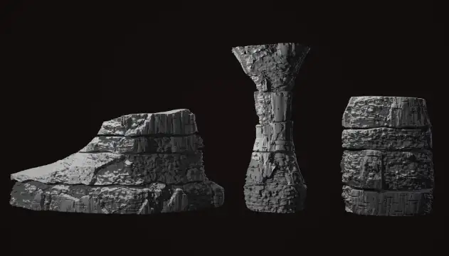
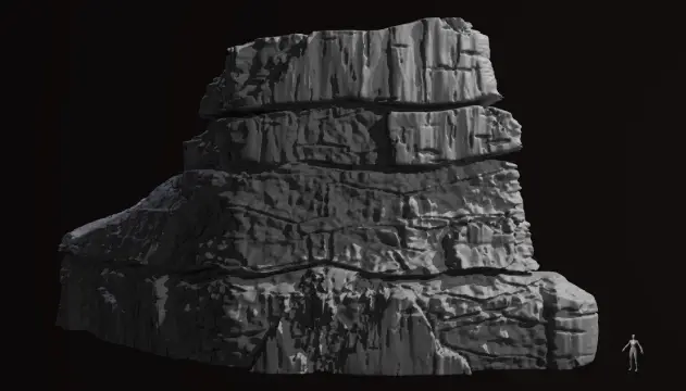
Cliff Generator
The Signal, Goose Byte
Houdini Tool
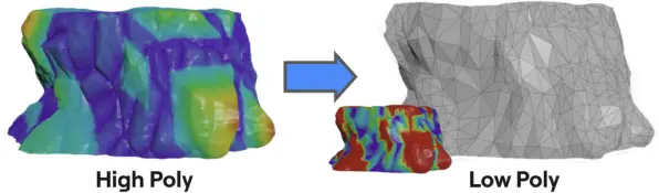
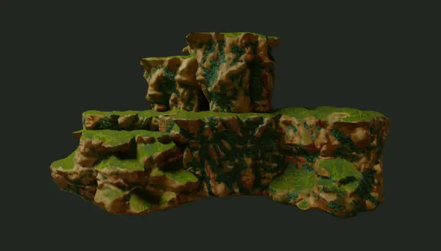
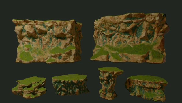
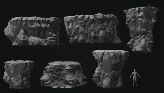
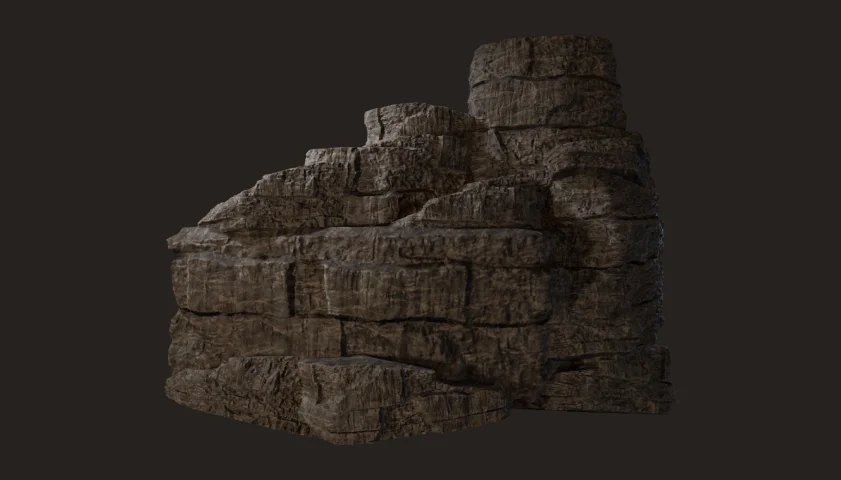
One of my first tasks was to create a procedural cliff generator using Houdini. By having a procedural generator, the team was able to create a set of modular cliffs and add new ones down the line. The generator takes in a base shape input, then creates a high poly cliff mesh with deformation and details. Then, a low poly version with collision is generated and textures are baked. The generator also properly names the asset according to the guideline set by the team for organization.

Base Shapes by: Shanah Sportellini
Materials & Textures by: Sarah-Frédérique Schetagne

Workflow

This was the workflow for the cliff generator, allowing the quick creation of multiple modular cliff assets with varying shapes and sizes. Here are the high level steps:

  • Base Shape Input: Sets of base shapes were created by Shanah Sportellini, the team's level artist, covering different shapes and size types. For example, medium cliffs for platforms and large cliffs for walls or background pieces.
  • Cliff Generator: The cliff generator then uses these base shapes to create the high poly cliffs, applying noise deformation and other processes to shape the details. The generator provides various parameters to the artist to control how the base shape is manipulated and deformed. Furthermore, it automates the creation of the low poly mesh, UVs, texture baking, and file naming, while also providing control to make sure it adheres to the team's agreed upon standards.
  • Output: The output is a low poly mesh to be used in engine, a high poly mesh as backup, and textures to be used in game or to create other textures by another team member.  The file name is automatic, either using the base shape's file name as a base or a new custom name.

General Features

These are general features that are shared between the generators, including things for quality of life, workflows, and exporting. Some of these features were not planned for the start, but were solutions to issues that surfaced and weren't thought of during development. A lot of iterations were made, ensuring that using the tools were as easy as possible.

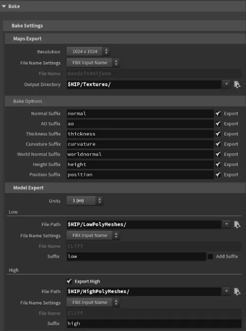
File Export and Directory

The export path parameters for FBX Output and Maps Baker is very basic, requiring the export path, file name with  extension, and expressions for texture baking.
I wanted to simplify the process by automating some aspects and add some naming flexibility. Furthermore, the base shapes files provided are already named properly, so I can definitely put that in use.

  • Allow users to use the input name as the export name. The file extension is replaced for textures and suffixes can be added depending on the team's naming standards.
  • Custom names are allowed as well, can be chosen from a drop down menu
  • A folder path input is provided, separating the export location from the file name.
string lowExportPath = chs("lowFilePath");
string lowCustomFileName = chs("customFileName");
string lowSuffix = chs("lowSuffix");
string fbxInputName = prim(1, "name", 0);

string fileName;
int lowFileNameSetting = chi("Low_File_Name_Setting");
int addSuffixSetting = chi("Add_Suffix");
lowCustomFileName = replace(lowCustomFileName, ".fbx", "");

if(lowFileNameSetting == 0)
{
	fileName = fbxInputName;
}
else
{
	if(len(lowCustomFileName) < 1)
    {
    	lowCustomFileName = "NO_NAME";
    }    fileName = lowCustomFileName;
}

if(addSuffixSetting == 1)
{
	fileName += "_" + lowSuffix;
}

s@lowFinalPath = lowExportPath + fileName + ".fbx";

High Poly Count Setting

When converting the mesh to high poly, VDB to polygon is used. However, VDB nodes only offer voxel size as a parameter, while setting a certain poly count is much more intuitive for me and other artists. Furthermore, there was an issue when selecting a larger asset, where the polycount would sky rocket and crashed my computer.

It would be much better if poly count is consistent no matter what size the object is. Because of that, I approximated the size of the voxel based on a target poly count and surface and programmed it with VEX.

int polyCount = chi("Poly_Count"); //value obtained from a parameter

float voxelDensity = polyCount/(f@totalArea * 1.25);  //final polycount overshoots quite a bit, and I found increasing the final area by 25% results in a close enough poly count
float voxelArea = 1/voxelDensity;
float voxelSize = sqrt(voxelArea);
  • The density of the voxels or grid can be obtained from the dividing the poly count over the total area
  • With the density, the area of each square or voxel can be obtained by dividing 1 over the density
  • The square root of the individual square or voxel area, is the length or size of it

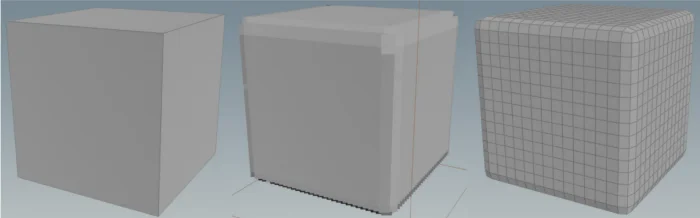
When converting VDB's to polygons, on a regular shaped mesh (like a cube), the end result is a mesh made out a grid of evenly sized squares. The size of those squares corresponds to the VDB's voxel size. Because of that, the amount of polygons can easily be deduced from the area of the mesh and the are of the square. However, for irregular shaped meshes, like the cliffs, I found that multiplying 1.25 to the mesh total area makes the final poly count close to the target.

This setting is not intended to be very accurate, but to make using the tool easier and safer. In those terms, I think it's good enough.

Low Resolution Toggle

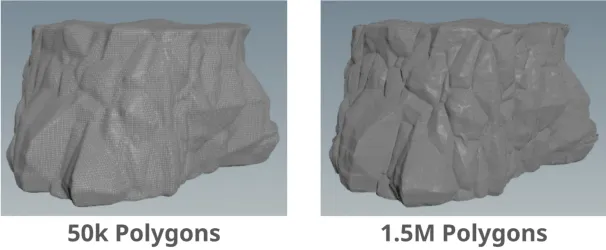
While tinkering around with parameters, I quickly found out that a detailed high poly mesh can take long time to update, increasing iteration time and causing frustration. Because of that, I made a low resolution toggle to make the mesh use a lower poly count version.

  • The mesh will be processed with a much lower poly count at around 50-100k instead of 1-2 m. You generally don't need to have dense a mesh to see the large changes.
  • Some nodes/steps are skipped as the effects are minimal at low resolutions
  • Once the overall shape is done, low resolution mode can be unchecked to view the smaller details
  • Clicking the render button will automatically disable the low resolution mode

After optimizing the generator leter on in development, this feature was not as critical, but it was useful for the initial stages.

Creating the Low Poly

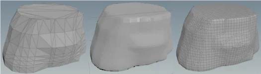
The total noise applied to the mesh is saved throughout the generation and is used to help guide the low poly mesh creation. To keep the protruding shapes, total noise is used as a weight parameter in the Polyreduce node. This makes the polygon density of the larger shapes higher, keeping its shape.

Height Multiplier

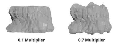
Some cliff meshes were used for decoration, others served as surfaces for the player to stand on. The latter requires the topside to be almost flat, so a noise height multiplier is added to allow this.

Overworld Cliffs

The first area of the game, contains cliffs with large and sharp pertruding shapes on their surface, emulating the effects of rock breakage. The end product is a modular kit of cliff meshes that can be arranged in different ways to create unique formations. A lot of iterations were made during this generator's development, making sure that it is as artist friendly as possible.  

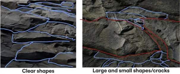
I was given reference images and found some my own to help create the Overworld Cliff Generator.  The cliffs have sharp faces with a somewhat long rectangular shaped patterns.  With the stylized look the game is going for, the cliffs should have clear shapes, with micro details coming mostly from the texture.

Noise

Images obtained from Quixel Megascans

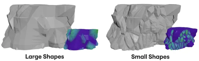
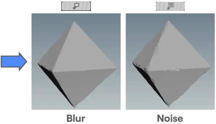
With the high poly version base shape, the first set of noise is applied. This creates the larger shapes on the mesh. Then a second set of noise for smaller shapes in between the larger shapes. When combining the two sets of noise, the maximum value between the two in a given point is used. After that, a final layer of noise is applied to add some texture.

Edge Wear

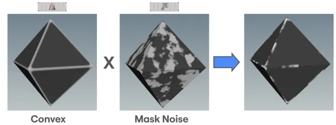
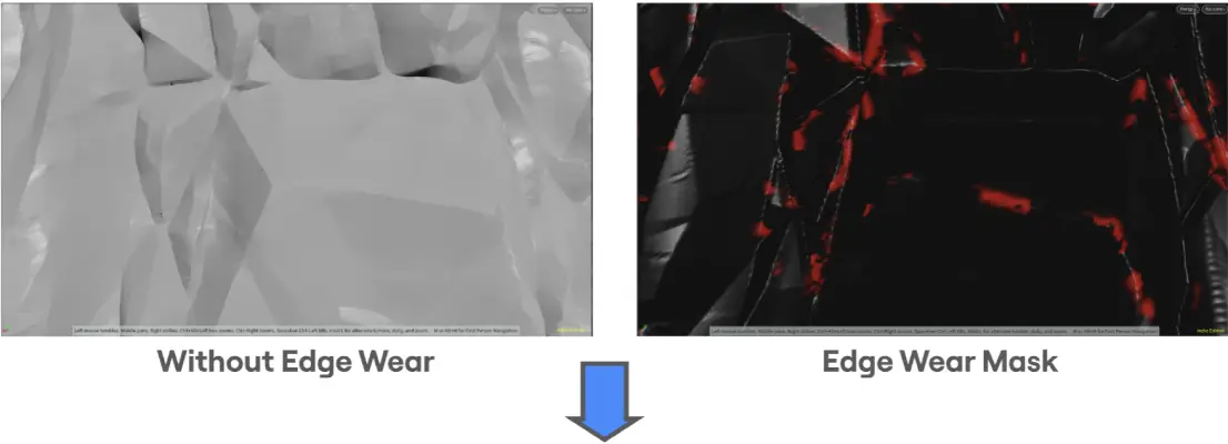
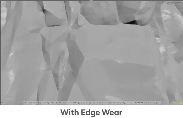
Sharp edges on rocks generally erode and break first from weathering. Because of that, I added edge wear to make the surface look more natural and breaks the pattern of the edges.

REMOVED: Voronoi Fracture

An earlier version of the generator used to do a voronoi fracture to create the surface shape. While it does create some interesting results, it wasn't really what the team was looking for, making look too busy. Furthermore, its difficult to make sure that the final silhouette doesn't steer too far away from the base shape given.

Scorched Rifts Cliffs

The second area of the game, taking place in an area filled with caves and near a volcano. The generator creates layers, flat shapes, and cracks on the cliff surface. The same as the overworld cliffs, different meshes can be combined to create unique formations. This generator reuses a lot of features from the overworld generator, especially quality of life and export features.

The cliffs in this section is mainly based on the Mammoth Cave, which reference images was given to me. The walls contains visible layers with clear seperation lines, with part of the wall being flat and mostly smooth, while other parts are rough.

Layer Effect
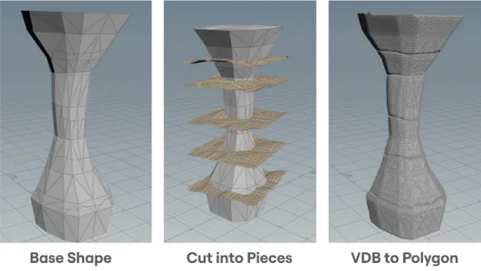
The base shape is cut into somewhat evenly spaced pieces using deformed grids and a boolean node. For every layer or piece, convert to VDB with a large voxel size, then to convert to polygon. This smooths out the edges and makes the separation clearer.
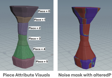
To make sure that each layer has separated surface detail, each layer's noise position is offset by a piece attribute, or a index number for each layer. In VEX, it would look something like this:

v@alteredP = v@P + i@piece * 5.235; //5.235 is just a random constant

Later on, the location attribute in the noise node will use alteredP instead of just P. This makes each layer's noise disconnected from one another.
An example where this is used is on the next step for a noise mask, which controls which parts have flat smoother surfaces and  rough surfaces. The mask generated are disconnected for each surface, enforcing the idea that these are separate layers.

Noise
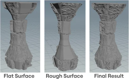
Using the noise mask, the mesh will have two different sets of noise applied: