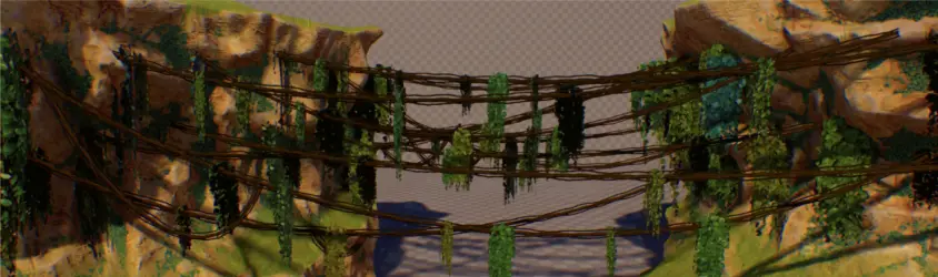
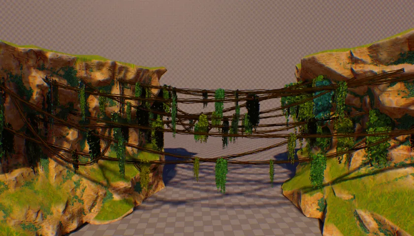
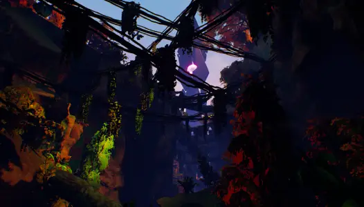
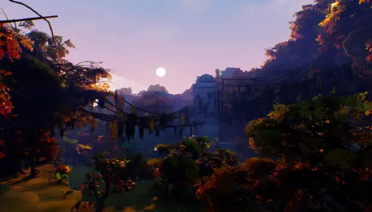
PCG Implementation & First Version
There were a lot of challenges when making this tool. I have barely used the PCG component at this moment and the procedural mesh component took quite a bit to figure out. Fortunately, my Houdini experience greatly accelerated my learning the new tool, and my mindset was as long as I know how to manipulate the attributes, it should be fine.
Furthermore, I used Unreal Engine's Cassini sample project to learn PCG and use it as base insipration on how this tool should work, as it is somewhat similar. I still needed to change a lot of its part to fit my needs, but it was a good start.
Set Start and End Points
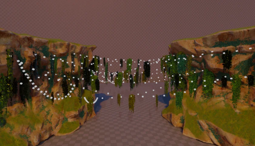
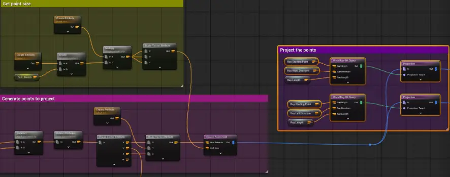
The tool uses a bounding box to control where the vines will spawn, putting points towards the left and right that serves as start and end points. At first, I used the World Ray Hit Query node with a Surface Sampler, but it didn't work as I expected on vertical surfaces. I looked up other ways to place points on a surface, then I found the Projection node and it was exactly what I needed.
Start and end points are created through these steps:
- Create a grid points along the forward and up axis of the volume
- Two World Ray Hit Query nodes, one has rays going towards the right of the volume and one going the left
- With the projection node, the world ray hit query is set as the projection target and the points from the grid are projected to the target
Adjust Start and End Points
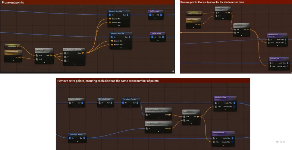
After the points have been created and place, points need to be cleaned up and randomized before the splines are created
- Points are randomly deleted, amount is controlled through an exposed parameter
- Points hanging too low in the bounding volume are deleted to ensure everything stays inside of the volume
- Both sides need to have the same amount of points to prevent any issues further down the line. So, the number of start or end points left out is the minimum number between the two
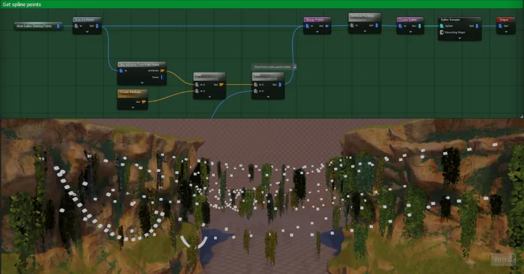
- Each start point gets a unique random end point to ensure good coverage. To achieve this, a random float is assigned to each end point and then they get sorted based on this random float. This scrambles the end points' selection order when creating the splines. The index number of the start point and end point is saved as a separate attribute called "indexBackup" to be used later when constructing the splines.
After optimizing the generator leter on in development, this feature was not as critical, but it was useful for the initial stages.
Spline Bend with Arrive and Leave Tangent
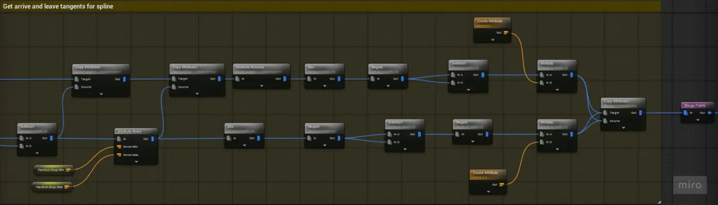
Arrive and leave tangents controls how the spline bends. The start point uses the leave tangent, while the end point uses the arrive tangent. The value of the leave tangent is a vector from the start point to the middle and goes downwards, the arrive tangent vector is a vector from the middle to the end point and goes upwards. In the implementation:
endLocation - startPoint = startEndVector
startEndVector.z -= randomDrop
leaveTangent = startEndVector * 0.5 * {0,0,-1} //goes downwards
arriveTangent = startEndVector * 0.5 // goes upwards
By the end, the start and end points are combined into one group with their previous indexes saved an attribute.
Spline and ISMs
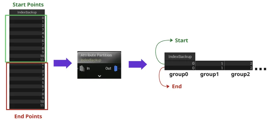
With the merged points and through the use of the "indexBackup" attribute created two steps before, groups of start and end points pair are created using the attribute partition node.
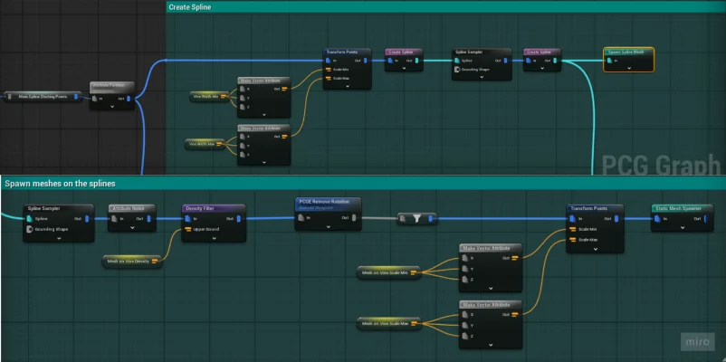
The last thing in the process is to create the spline meshes and decorations attached the spline like leaves. The combined points group are partitioned into groups of two members, one start point and one end point. The groups are split based on the saved index number.
After that, the splines are created and a spline sampler creates points in between, used for the spline mesh and decoration ISMs.
Profiling, Performance Problems
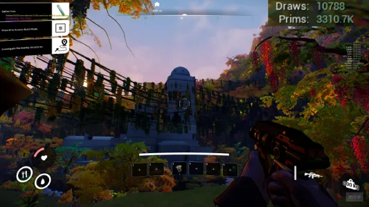
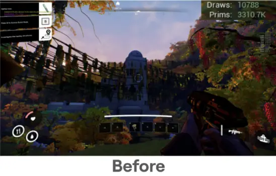
After all of the vines in the level has been paced, I started profiling the scene. I noticed that some areas have draw calls and poly count increase drastically, and quickly realized that its the new vines was causing the issue. The polycount for the vine model was not fit for this kind of heavy use and each segment of the spline mesh takes up a draw call and is relatively high in polycount.
Updated Version with Procedural Mesh
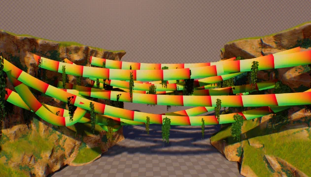
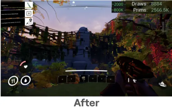
The art lead (Gimli Damian Orawiec) suggested to look into procedural mesh component for Unreal Engine and I thought it would be a great solution. Furthermore, since the vines are placed quite far from the players, ribbons instead of tube meshes would work well. After doing some research and testing, the procedural mesh component could easily be added with some additions to the generator.
Preparing the Points
I reused the points for the the spline mesh as positions for the new vine's vertex positions. The sampled points are connected to an output node to be used in a blueprint with a procedural mesh component.
Procedural Mesh
After the PCG Component has completed its task, it can run a function from the blueprint by putting the function's name in the "Post Generate Function Names" section. So, after the PCG Components is done placing the ISM's, the function that creates the procedural mesh is ran.
Getting Point Data from PCG
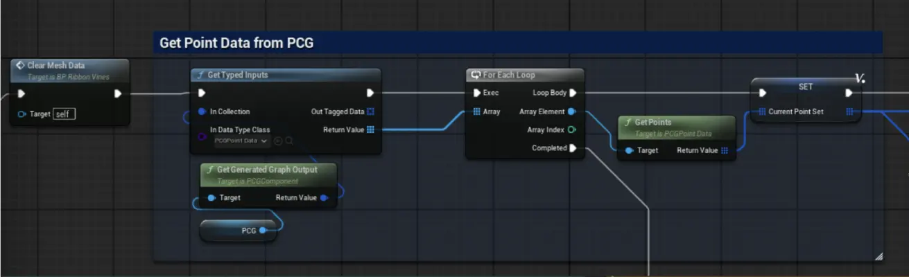
To get the sampled points from the PCG Component, a Get Typed Inputs node is used with the PCG Ccomponent connecte, getting the PCG Point Data. This gives an array of groups containing the sampled points of each splines. A for each loop is ran to get the position of the sampled points on each splines.
Generating the Mesh
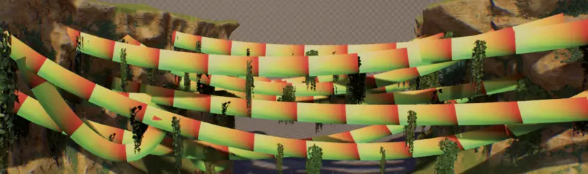
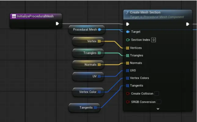
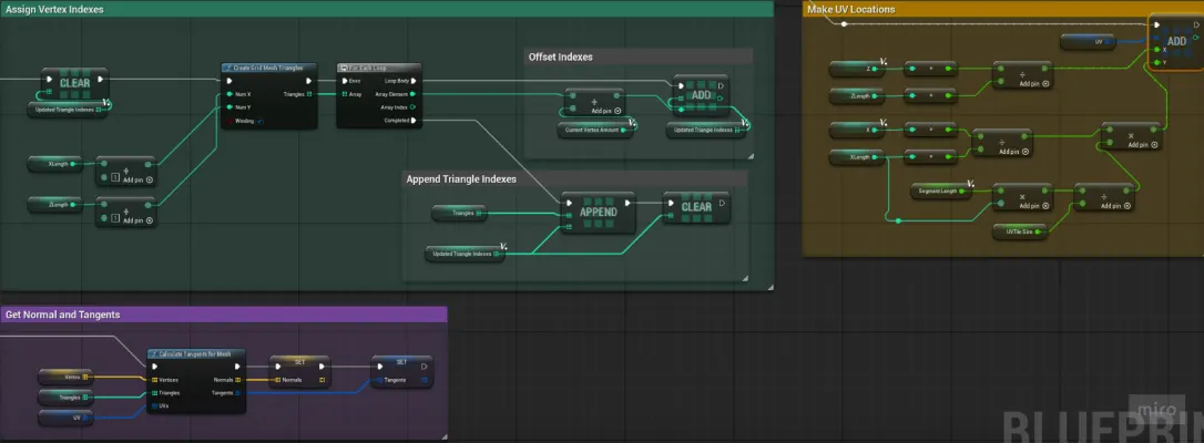
With the help of Unreal Engine's demonstration video on the procedural mesh (https://www.youtube.com/watch?v=1ksgB6hYGrE), I was able to easily apply the mesh generation setup for my situation. Using the points generated from the splines, the Blueprint constructs ribbon meshes by generating vertex positions, defining triangle indices, assigning UV coordinates, and calculating normals and tangents.
I also looked into dynamic mesh, which is newer. However, I found it less intuitive for this scenario and chose use the procedural mesh component instead.
Material
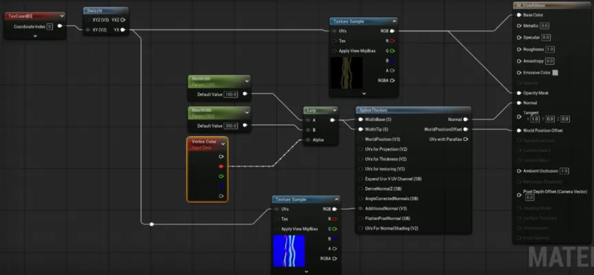
In the vine material, a spline thicken node is used. This creates a 3d effect on the ribbons and makes them face always face camera. With the vines being generally far from the player's reach, its barely different from using cylinders meshes. While generating the procedural mesh, each spline gets assigned a random vertex color to randomize the widths of the vines.